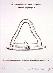
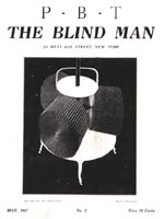
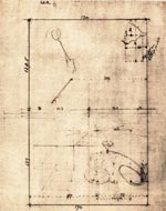
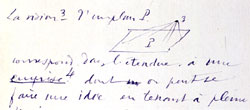
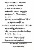
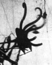
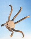
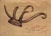
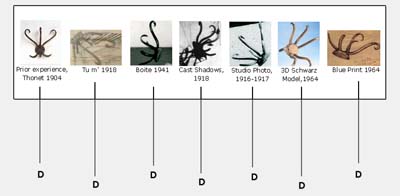
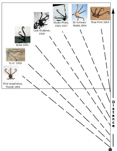
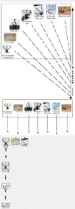
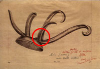
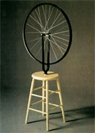
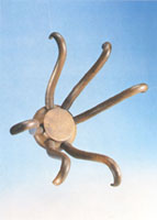
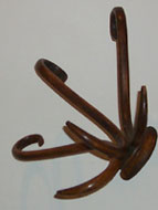
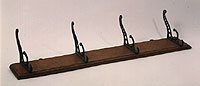
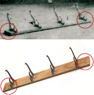
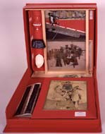
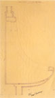
Duchamp states innotes written between 1911-15 (see illustration 1, showing Duchamp’sGreen Box Note published in 1934) that the time and date of hisreadymades is important “information” in addition to the “serialcharacteristic of the readymade.”(1) The “snapshoteffect”(2)of this timing of the readymade, to which Duchamp refers in this note,makes sense when we examine Duchamp’s readymades with his mathematicalnotes (written 1911-15 but held back for publication by Duchamp until1967, a year before his death.)(3) First, let us begin by “looking” at Duchamp’s readymades through time. Since Duchamp claims that he “lost” most of his original readymade objects, Duchamp’s 1915 hatrack, as well as his urinal, snow shovel, coatrack, bottlerack and bicycle wheel and stool, exist only in a series of varied representations given to us by Duchamp over an extended period of time. As an example, the following time-line illustrates the sequence of appearances of Duchamp’s “lost” hatrack. We see “the serial characteristic of the Readymade” just as Duchamp described in a presentation of his “Readymade” (the title he used for his hatrack in the 1941 representation, see illustrations 2A, B, C, D, E, and F below).
Thus the tally of Duchamp’s hatrack representations is as follows: 2 2D shadows 2 2D photographic images 1 2D blueprint (1964) In effect, Duchamp gives us only 6 “snapshots” in time of his Hatrack Readymade (with “all kinds of delays”)(4).The limited total of information that we have, obviously, does not equal the quantity of data that we would have if we had access to the lost 3D original or if we suddenly possessed many more 2D photographs that carefully depicted the original 3D hatrack “in the round.” Indeed, with the paltry set of data that Duchamp provides, the only physical or mental construction we can make, based upon the hatrack’s original form, is by fusing or averaging and filling in among the 6 representations previously listed — 5 images in 2D and 1 model in 3D. This procedure can be done mentally via visualization, or physically via model-making, with conscious effort on the part of spectators. However, interpreting 2D depictions, mentally translating them into 3D, and then rotating and joining them (with visual filling in), is not a skill equally possessed by everyone and has, in fact, been frequently used as one measure of intelligence.(5) Alternatively, if we do not help ourselves by consciously combining the 6 hatrack depictions, the result is an ad hoc, automatic conclusion or assumption-generated “readymade” from the unconscious mind. A single depiction — such as the first Duchamp hatrack that we see in a photograph or a print, or the 3D Schwarz model, or any one of a combination of Duchamp’s 6 particular depictions — has served to evoke in our minds a “general idea of a Duchamp hatrack” that is surely derived from an uncertainmixture taken from among Duchamp’s 6 hatrack representations and our prior experience with hatracks. But does our present “generalization” or “knowledge” of Duchamp’s hatrack hold up to testing? In other words, will the generality that we have made about Duchamp’s readymades, and have long held inour minds and in our written art history — that such readymades as the hatrack are simply store bought, unaltered, mass produced objects — be maintained after more snapshots are added to the 6 that we havealready tallied. Yet, you may challenge: how can we add more snapshots to our generality when Duchamp gives us only 6 representations and the original is lost? Herein lies the key to Duchamp’s insight, conveyed within his In the Infinitive [a.k.a. the White Box](1967) mathematical notes (1911-15). After identifyingthe 6 representations that Duchamp has given us as 6 distinct and separate snapshot views of his original hatrack, we have, essentially, a set of 6 “cuts” or 2D parts taken from a larger set of information,or the hatrack as a 3D whole. These 6 “cuts” are, in essence, 6 perspective views or observations. Each cut is also, itself, an “aggregate” (made of parts) of additional “cuts” or observations — ad infinitum. In other words, to add more cuts to our set of 6 hatrack representations, we must simply repeat our previous operation. Just as we took 6 cuts (parts), beginning from our generality of Duchamp’s hatrack, we must now take these 6 cuts (now themselves a set or whole) and cut each of these cuts into more cuts.
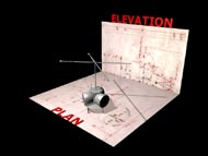
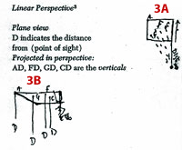
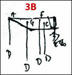
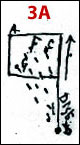
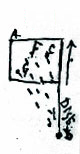
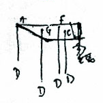
Duchamp clearly indicates his grasp of this recursive nature of our mental operations in the White Box Notes. Several drawings illustrate two perspectives that behave as one process split into two alternating mental states. Our perspectives mechanically move back and forth between the general (a single perspective of the AGFC figure, see illustration 3A) to the particular (multiple snapshots [cuts] or perspectives of A,G,F,C in a series over time, see illustration 3B). Immediately after perspectives A,G,F and C are cut as in figure 3B, we have created a new set that functions as a generality, as in figure 3A.We then begin the cycle all over again, with more cuts of this generality,then another generality, then cuts in a series, again at finer and finer scales. Essentially, we are mentally and observationally moving back and forth between states 3A and 3B — wholes and parts at different levels of details. Illustrations 4A and 4B show how the schematic diagram of Duchamp’s two mental operations contained in illustration 3A and 3B apply to his hatrack. Illustration 4A matches the relation of the single perspective in 3A (Here Duchamp’s hatrack in particular, and prior experience of hatracks in general, are fused together), whereas illustration 4B matches the relation of a series of perspectives taken over time as in 3B (Where Duchamp’s hatracks are reduced to multiple but discrete snapshots in a time-series). Illustration 4C depicts a possible series of mental steps that could occur immediately after 4B. This series illustrates how we now cut each of the 6 cuts from step 4B into more cuts, at an even finer scale of observation, ad infinitum. click images to enlarge
As in 3B and 4B above As in 3A and 4A As in 3B and 4B As in 3A and 4D Step 4 of illustration 4C above answers the challenge previously mentioned: how do we add more cuts to our limited set of 6 representations of Duchamp’s hatrack?
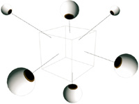
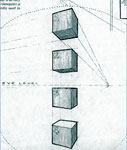
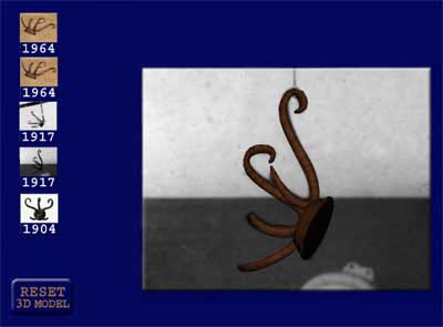
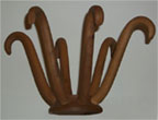
When we actually take Duchamp’s hatracks representations and add the cuts (beyond merely identifyingthe 6 snapshots as in step 2 in illustration 4C), we discover that everyone of the 6 representations (5 in 2D and 1 in 3D) is not, as we mighthave expected, a single cut from the same 3D hatrack object. By wayof example, see illustration #5, if we reassemble all observations (cuts)resulting from the set of all eye positions looking at this particularcube, we would be able to predict, and easily to build, a symmetricalcube object from the resulting limited set of cuts. Each cut, upon examination,fulfills our expectation of a cube’s form with its 6 faces, 12 edges8 vertices — all we have to do is just count them to confirm. Illustration#6 depicts how the perspective distortions change according to the angleof eye’s observation of the cube. Our expectations arenot fulfilled upon examining the 6 hatrack snapshots. Not only are thecurvatures of the hooks different in all 6 representations, but we mustconclude that even the number of hooks varies after we count them. Forexample, the Schwarz 3D model, (the “corrected” second version)has 6 equal length hooks, symmetrically placed as 3 on one side and3 on the other side of the base’s circular form. In contrast, the blueprint(approved and signed “okay, Marcel Duchamp”) has a weird tangleof 2 long and 3 short hooks. click images to enlarge Click here for Interactive Presentation Interactive Software Instructions: Please test out the interactive hatrack software thatwe have installed(6).To select a hatrack click on one of the 5 icons shown on the upper left.Hold the left side of the mouse down. Making sure the cursor’s handicon switches on (while the arrow is moving) roll the mouse on the hatrack’sround base and “pull” the 3D model off its fixed position in the 2Drepresentation. Interactive challenges include; the 1941 print of astudio photo (and an early stage of our hatrack 3D computer model),the 1917-18 studio photo (and an early stage of our hatrack 3D computermodel), the 1964 Schwarz blueprint (with a computer model of the Schwarz3D version), the 1964 Schwarz blueprint (with an early stage of ourhatrack 3D computer model) and, a 1904 Thonet hatrack catalogue diagram(and equivalent 3D computer model)(7).To explore these 5 models, keep the left side of the mouse down, (alwaysbeginning with the hatrack’s base) and roll the mouse in various directions,and compare the 3D shape of the hatrack to the 2D representation. Rotateeach of the 5 hatrack 3D models in all x, y and z directions that arepossible in 3D space (north, south, east, west, up and down). Try tovisualize the 2D representation that you choose as a 2D slice (cut),or only one fixed perspective view of the 3D hatrack form. Also, practiceplacing the 3D models back into the best possible position matchingthe 2D depiction you have chosen. The 5 computer modelsshown in the hatrack interactive design result from early stages ofour geometric analysis of the 6 hatrack representations in combinationwith our research of available mass-produced hatrack models in the historicalrecord (found in period catalogues, patents, museum collections anddesign books). The 5 interactive hatracks are meant to offer spectators a shortcutand assistance in their efforts, not only to review my arguments butto allow them to experience, and to explore and build upon their ownanalysis to process, and later to generalize from the facts before us. The order of occurrencesand the quantity and choice of 5 interactive models above differs fromthe earlier illustrations #2A, B, C, D, E, and F that I originally sitedas Duchamp’s 6 hatracks cuts. For clarity, I will discuss each of the5 interactive models separately starting with the 1904 Thonet catalogueimage and 3D model. What To Look For: 1. 1904 Thonet Hatrack – Interactive Model After examining Duchamp’s 6 hatrack representations, and after canvasingthe historical record, I concluded that; A. Six different 3D hatrackswere described by Duchamp’s 6 representations (five 2D, one 3D); B.No duplicate, mass produced, readymade store-bought hatrack matchedany of the five 2D representations or the one 3D Schwarz model. C. Theclosest possible mass-produced hatrack circa 1915 or before that I couldfind (after considering the varied deviations within the five 2D depictionsand the one 3D model), was the common Thonet bentwood hatrack (a designstill commonly found today in both metal and wood). 4 Hatracks from the Art Science Research Laboratory (ASRL) Collection
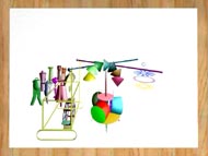
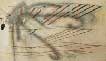
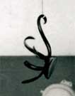
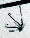
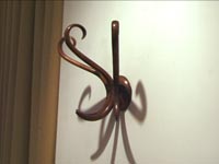
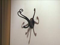
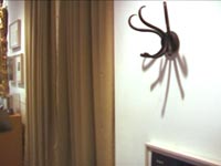
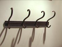
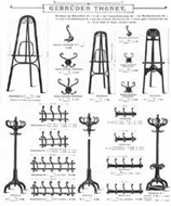
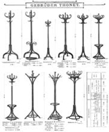
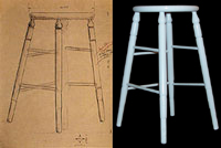
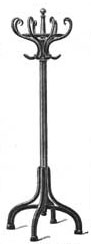
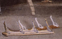
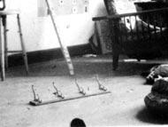
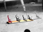
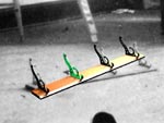
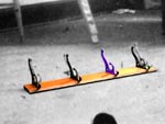
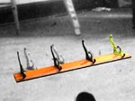
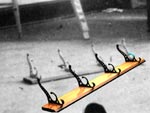
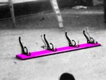
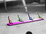
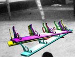
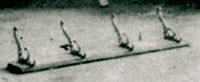
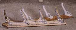
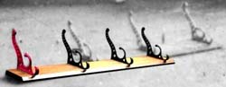
See illustrationsand videos 7A, B, C, and D showing lab members hanging hats on fourhatracks from the Art Science Research Lab collection. The first woodmodel below is the closest one that we have found that has characteristicscommon to all six of Duchamp’s hatrack representations, and appearssimilar to Thonet bentwood style #11022. Thonet Brothers mass-manufacturedand shipped their original Bentwood designs throughout the world. Seeillustration #8A, B showing the title page for the 1904 catalogue andthe page for hatrack #11022. Trythe Thonet 1904 interactive 3D model. Note how symmetrical thehatrack appears and how it matches the catalogue drawing. The patented technologythat allowed Thonet to permanently shape wood for furniture withoutcarving (hence bentwood), became immediately recognizable by the “S”curve module units. Note too, that the illustration 7A Thonet hatrackhas three “S” curves on a round base. The 7B and 7C Thonet-stylehatracks, one in metal and the other in wood, also have 3 “S”hooks. Click to see videos of each hatrack in the ASRL collection. Theillustration 7D video shows the official Thonet paper label on the back.As you can see from all 4 videos, each of the hatracks are wall units,and each can easily hang hats. BothThonet catalogue pages illustrations #9 and 8B show examples of thecommon bentwood hatrack/coatrack free-standing models still in use today. click images to enlarge
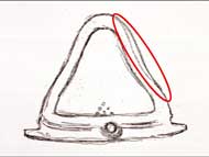
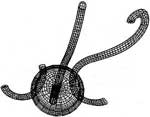
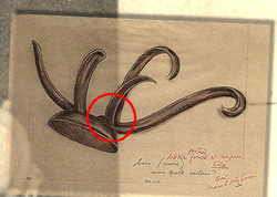
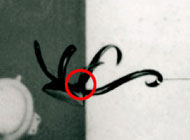
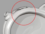
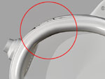
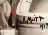
This studio photograph was reproduced as a retouched print in the 1941 Boîte en Valise. Count the hooks. There are 2 long hooks and 3 short hooks. We took the 3D model of the Thonet hatrack with the 3 “S” hooks, compared it to this studio photograph print and noted the differences. If the first long hook and short hook are, together, one “S” hook of the Thonet model (with a total of three “S”s), then the second long curve and short curve could together be the second “S”. But the second long hook (having a much more open and soft curved shape when compared with the first long hook’s curve) cannot be the same shape as the first long hook. Rotate the 1917 (above the Thonet 1904) interactive hatrack 3D model away from the 2D photo underneath and compare the differences. Note that the 3D model’s second “S”‘s long curve is not open and soft like the second “S”‘s long curve in the photograph(8). Yet, the second “S”‘s long curve in the 3D model approximately matches the first “S”s long curve in the photograph. Moreover, the 2nd”S”‘s bottom, small hook is a wider shape and less curvedwhen compared with the first “S”‘s bottom small hook. Finally,the third small hook is missing the top, long hook part of the “S”.In order to represent Duchamp 1917 2D depiction in 3D, we had to cutoff the long curve from the “S” hook and leave the bottomsmall hook curve in yet a different angle from the first and second”S”‘s two bottom small hooks. See illustration #10 that showsa front view of this hatrack with its cut off long hook. Rotatethe interactive 1917 3D model into the face forward position (like theThonet 1904’s position) and then go back to compare the Thonet 19043D model. Importantly, try to place this Thonet 1904 into similar positionsas the first or second “S” hooks in the 1917 Duchamp 2D depiction.(The 3D Thonet model here is slightly squatter than Duchamp’s 1917 hatrack.) 3. 1917 Hatrack (3rd Interactive hatrack model from the bottom) This studio photograph immediately appeared to be a more promising matchfor both the Thonet 1904 model and the 1918 shadow in the Tu m’ painting(see illustration 2A). However, all attempts to match a 3D model withthree identical and symmetrical “S” curves to the depictionthat Duchamp provides failed, asone can see by examining this 1917 Interactive 3D model. Again,return to the 1904 Thonet 3D model and try to place each of the model’sthree “S” hooks into similar positions as the 1917 hatrack”S” hooks found here. As observed in the previous 1917 photo(2nd hatrack from bottom), the Thonet 3D computer model has tightercurves and shorter hooks then in our actual wooden Thonet 3D model fromthe ASRL collection shown in #7A. 4. 1964 Blueprint with Interactive 3D model of lost version, Schwarz 3D Hatrack model This blueprint turns out to be a poor interpretation made by an anonymousdraftsman while tracing the 1917 Boîte en Valise (see illustration11A, showing overlay of 1941 Boîte hatrack [placed on its side]with the blueprint. See the circled section on #11B and compare thisto the circled part of #11C, instead of interpreting the first smallhook (from the right) making a continuous “S” shapemoving from the first long hook on the right, the blueprint indicatesthat the 1st short hook is a separate piece awkwardly sticking out fromwithin the side of the first long hook. It is interesting to note thatthere is no indication of the draftsman having had a conception thatthe hatrack was made of “S” shapes anywhere in this muddleof 3 small and 2 long hooks, (with each hook having its own size andunrelated curved shape). click images to enlarge
My examination ofother 1964 blueprints for other Schwarz readymades might be helpfulto mention here. Also signed “Marcel Duchamp, okay,” the bicyclestool blueprint is similarly ambiguously and inaccurately drawn (mostlikely because Schwartz’s draftsman did not know how to interpret thebroken legs and rails as depicted in the 1941 Boite-en-valiseprint of the bicycle wheel (also showing the coatrack). See illustration#12A, B and C, notice that the two most right horizontal rails in theblueprint go in two different directions and are cut off oddly, as depictedin the original studio photograph (12C). In addition, the 3 legs arenot evenly spaced as one would expect in a blueprint (and the fourthleg is missing completely) and yet in the final Schwarz edition (12D),all legs are completely symmetrical. Note that illustration 12B alsocontains the within 3D model we made using the information containedin the 1964 stool Blueprint (also 12B). click images to enlarge
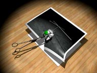
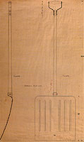
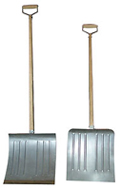
The shovel blueprintindicates that the handle was literally traced from a well known ManRay photograph that captured the shovel hanging high above eye level,(see illustration 13A and B). At this height, as the eye looks up theshovel’s wooden shaft’s outside edges appear to converge (and get narrowerwith more distance.) To create a blueprint, perspective distortion mustbe accounted for (and discarded) if you use a photograph as a sourceto recreate an accurate 3D model. See the shovel blueprint illustration13B, the front and side elevation views both depict the converging linesthat were later, amusingly translated in the construction of Schwarz’s3D model. The shovel’s wood shaft, literally gets progressively morenarrow from metal blade to the handle. See illustration 13C showingthe final Schwarz 3D model built from the blueprint as a much smaller3D model on the left than the shovel on the right that was built frommeasurements of actual example of the Schwarz edition of 8 snow shovels)(9). click images to enlarge
Let us return to the hatrack blueprint 1964 and the 3D model. IfSchwarz’s 1st version of the hatrack 3D model, indeed, looked like thegeometry in this blueprint, it’s no wonder why Duchamp insisted uponthrowing it out and felt he had to redesign it.. . and yet his 2nd andfinal version of the Schwarz hatrack looks even less like the photographsof the “original” 1916-17 hatrack in his studio! (I will laterdiscuss the likely reason why Duchamp approached his hatrack in thistechnique of “information” that decays in a series of snapshotsover time). 5. 1964 Blueprint with Interactive version of 3D Schwarz model
click images to enlarge
Compare5 Interactive Models with Tu m’ and Cast Shadows Depictions
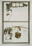
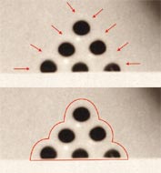
The final 2 representations from Duchamp’s 6 depictions thatwe will discuss are Tu m’s 1918 hatrack and Cast Shadows‘hatrack, 1918. These are both shadow projections that can also be comparedto five interactive 3D models (1904, 1917, 1917, 1964, 1964) The Tu m’ shadow’s2 long hooks and 3 short hooks, in particular, (see illustration 15A,B) if viewed upside down and then compared to the 1904 Thonet modelwhen rotated into similar position, can readily be seen as fragmentsof 3 “S” shape hooks (albeit, that the 3 “S”‘s inTu m’ are incorrectly and asymmetrically angled in relation toeach other and the top of one is cut off when compared to the Thonet1904 3D model below). The 1918 Tu m’ painting brings us back to the issue, previouslymentioned, of the difference in making objects in 3D, versus interpretingwhat these same objects look like, due to distortions, in a photograph,or in perspective drawings. Just as a bicycle wheel can objectivelybe perfectly round in shape and yet appear in a photograph as an ellipse,the same is true of any object’s representation. Representations mustbe interpreted. We, in fact, because of a prior experience, can safelyguess that the bicycle wheel is round but only appears to be an ellipsedue to perspective distortions. However, an alternative hypothesis couldbe true, though not as likely — that the bicycle wheel is not roundbut shaped like an oval. How can we know? The answer is two-fold. Ifwe have access to the original wheel, we can test it (roll it and seeif it smoothly and evenly rolls) and measure it (and see if the axisis in the middle of the circumference of a circle). In the case of Duchamp’shatracks and other readymade objects, we are in the same position ofdiscovering that a bicycle wheel that we assumed was round in a photographwas, in fact, oval. Since we only had a set of photographs of the secondversion of the Bicycle Wheel, and not the actual object, theonly thing we could do was to take measurements from the 2D representations,fuse and build 3D models (both physically and in computers) based uponthe group of photographs, and then test and measure again.
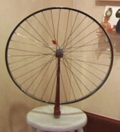
Ironically, my bicycle wheel example turns out not to be hypothetical. Seeillustration 16A, B. From the set of bicycle wheel photographs, afterwe made measurements and models, and tested them, Robert Slawinksi, inour ASRL group, concluded that the axis of the Duchamp bicycle wheel was,in fact, not in the center of the wheel! Duchamp had lengthened some spokesand shortened others to create a large and surprising effect that is basedupon only a very small difference in the decentered positioning of theaxis. Click on #16B to see the video of what happens when our 3D modelof one of Duchamp’s bicycle wheels turns(11). click images to enlarge
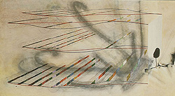
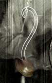
The Cast Shadows 1918 photograph shouldalso be examined by spectators in comparison with the 5 interactive hatrackmodels, see illustration 17. This representation of the hatrackindicates 3 long hooks and two short hooks. The first long hook on theleft, hanging by a string, ambiguously appears as if it could be attachedin a whole “S” shape with the first small hook on the left. A more likelyinterpretation is that the middle long hook is one “S” curve with thefirst (left) small hook and that the long hook at the most right is connectedto the right most small hook. Yet this is unclear for the right most longhook could share an “S” shape with the left most small hook. In additionto the hatrack shadow ambiguities, other ambiguities reign in this photograph.For example, Duchamp’s work Hidden Noise (see illustration 18A,a closeup of the Cast Shadows, 1918) oddly appears twice(he supposedly only had one original in 1918 — the multiple edition of8 was made much later in 1964, see #18B that shows the original HiddenNoise.) One has to conclude that Duchamp either somehow used mirrorsto multiply the Hidden Noise shadow, or he created a photographiccomposite where he layered different photographs together into one image(12).Duchamp used both techniques in his photographs, a topic we will explorein the next section. click images to enlarge
Duchamp’s readymade hatrack only Afterduly noting the geometric distortions in Duchamp’s six hatrack representations,we must conclude that the simple history and definition of the hatrackthat everyone believed — that a readymade is an unaltered, mass-producedobject — must be completely reassessed and rewritten. We can return to the six representations of the hatrack and explore some of the issues now raised such as to how Duchamp generated the six depictions? Did he alter hatrack objects or doctor photographs or both? We are presently working with forensic scientists to help us determine more about the exact nature and type of photographic or physical manipulations that Duchamp may have used. Duchamp, obviously, put us all on notice that he was doing the photographic tricks well known in the late 19th and early 20th century by both amateur and professional photographers, see illustrations #19A, B. In both photographs 19A and B, Duchamp himself appears to be a ghostly apparition, a typical photo trick of the time.(13) click images to enlarge
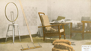
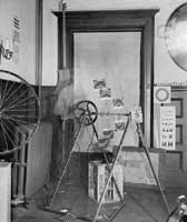
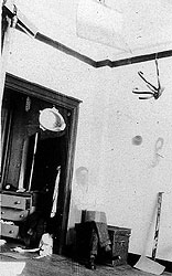
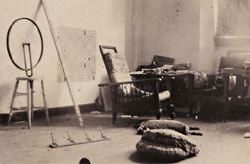
Forensic experts thatI have consulted also noted that the scale, shadows and light directionsin many of Duchamp’s photographs are inconsistent throughout the wholeimage.(14)As an example, strong shadows will, inconsistently, be cast from oneobject but not from the other object directly next to it. (Closely examineillustration 20A, Note that the stick leaning against the wall casta shadow and yet the Bicycle Wheel does not! Moreover, the pillowsin the foreground cast strong shadows and yet the Coatrack doesnot!) For another example, look at illustration20A, B and C. A full size snow shovel could not possibly be hanging physicallyfrom a height indicated in these studio photographs. We discover thatthe wood shaft would have to be too short when we compare the shovel’ssize to the ceiling. click images to enlarge
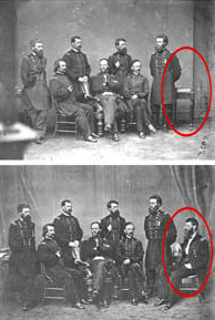
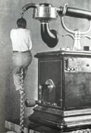
Our resulting hypothesismust be that the shovel’s wood shaft and handle have been somehow cutoff. Duchamp (or someone in his behalf) shortened the wood shaft eitherphysically or photographically. In the later case of trick photography,instead of hanging a short snow shovel in his studio, Duchamp, or someoneat his behest, could have; 1); taken a photograph of a snow shovel andcarefully trimmed away the background; 2), Next, this snow shovel shapedphotograph part (with short wood shaft) would then be inset into a preciselysized and shaped cut out receptacle in the studio photo’s emulsion (similar to putting acut out cookie back into its negative space within the rolled out dough);3), the studio background and shovel fragment now appear as one photographthat is rephotographed and printed for the final resulting composite thatwe see. Examinehere the video of the work, In the Manner of Delvaux (1942) whichdocuments only one example among many of the expert skill Duchamp (orsomeone at his request) demonstrated in creating photographic composites.(See Illustration 21A) Adding or subtracking subjects from photos wasdone with numerous techniques from the earliest days of photography. MathewBrady seamlessly added an eighth Civil War general in illustration 21B. The aforementionedstudio photographs (19A, B and 20A, B) present many other instancesof photographic manipulations that I will leave for future discussions.However, please see Stephen Jay Gould’s text box here to read his observationsand discovery regarding Duchamp’s studio photograph, illustration 19B.For now, I will limit myself to analysis of two studio photographs ofreadymades to continue my argument (see illustrations 22A and 22B thatshow Duchamp’s “original” 1916 coatrack and “original” 1917urinal.) click images to enlarge
Did Duchamp Give Us a Ghostly and Stephen Jay Gould
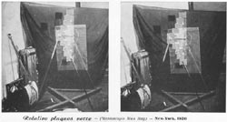
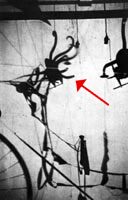
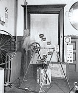
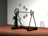
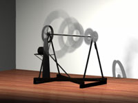
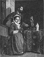
Man Ray’s 1920photograph of Duchamp’s Rotative plaque de verre (withone plate broken and scattered on the floor) raises many questionsthat have never been addressed by art historians. In particular,although the photo, at first glance, might seem to be a casualsnapshot of a messy studio, even a cursory examination revealscomplex changes, careful placements, and interpolations – particularlyto imbue the entire composition with a “circle” theme (understandablesince the centerpiece Rotatitive plaque is a device madeof glass rectangles that, when spun, produces the appearance ofa set of rotating circles.) But note all the other circles, not so casually placed or imported into the composition: the “target” beneath the chess pieces on the wainscotting, the circle cut out of glass in front of the frame on the floor next to the crate, the bicycle wheel to the left (but not resting on the stool that should be visible if the famous readymade roue de bicyclette just happened to be present in its reality and entirety, and, especially, the blurred circular forms that look like cooking pots with handles at the upper and lower right, and that create such an interesting triangular composition with the bicycle wheel at center left. (Thomas Girst suggests that these large circles may be parts of the lighting equipment that Man Ray set up to take the photo). One can go on ad infinitum: why, in an otherwise complete chess set of white pieces on the wainscotting, is a single pawn missing? Why is the Russian eye chart hanging upside down? Click to see video Animation of the Rotary Glass Discs in stationary position (left),
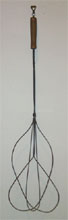
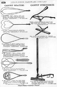
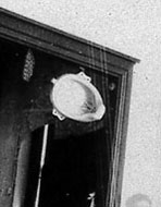
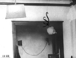
But moving to the main point of this note, look just tothe left of the large wheel at the left end of the rotative plaque. Herewe see a ghost figure of the top half of a man’s body, perhaps Duchamp’s.We can hardly make out the head, but we see the right arm fairly clearly,even including the creases of the shirt. The figure then cuts off abruptlyat the waist, but we can easily be fooled into missing the cutoff becausethe photo includes what seems to be an old-style carpet beater, businessend pointing down and handle pointing up, extending just where the man’sright leg would be. (Why?) Now, look abovethe right forearm just behind the shirt cuff. The image is blurry,but I’m fairly sure that I see a single full hook of a Thonethatrack (the presumed original for Duchamp’s series of manipulationsand redoings). I originally thought that the ghost man was cradlingthe hook in the crook of his arm. But I now think that the hookjust lies in front of the arm. The hook seems to be tied to astring extending rigidly upwards and affixing nowhere. The hookthen curves around to the right, passing over the figure’s arm,and then completing its curve just under the arm and towards thewaist. A second string seems to emerge from the top, under thefirst, and to run downwards and slightly to the left, finallypassing over the figure’s arm just to the left of the hook itself. click images to enlarge
Now, both Duchamp’s 1941 Boite print of a 1916-17 studio photo and a second studio photograph of the hatrack show the entire device hanging from the ceiling, affixed by a similar string tied near the upper end of a hook in positions comparable to the tie of the single hook in the ghost photo. (Duchamp, by the way, produced several photos with ghost images of himself emplaced into an interior scene). However,one of the two studio photos of the “full” hatrack in the 1941 Boite print seems to be missing one of the three large hooks. Did Duchamp remove the hook from this photo and then give it back to us as a single ghostly item in this later photo? Hooking and roping us in yet again; pulling our leg with his legless ghost; kicking us in the pants with a rug beater acting as a surrogate for a leg?
One, might think at this point, “So what. I can alreadysee that Duchamp probably altered, physically or photographically, hisreadymade objects — what difference does this make?” Let’s set asidethe fact that all books of art history or cultural criticism (and evencookbooks! See illustration 22C) state, as their premise, that Duchamp’sreadymades are unaltered, store bought mass-produced objects – and thatthis claim can now be dismissed as factually incorrect.(15)I will use illustrations 22A and 22B to show that Duchamp’s original coatrackand urinal help explain why I believe Duchamp altered readymade objectsin his photographs in the first place. Since the quality and approachthat Duchamp used for his numerous distorted “readymade” representationsare similar, such a frequency of occurrence suggests that Duchamp wasapplying a single geometric system. Perhaps this system that I have beenobserving throughout Duchamp’s readymade works is the new and mathematicallyrigerous “rehabilitated perspective” geometry Duchamp spoke about in interviews.Moreover, I also found evidence that Duchamp used this new geometry inthe Large Glass, just as he had claimed.
In a 1966 interview with Pierre Cabanne, Duchamp states:(16) Cabanne: It was no longer realistic perspective. Time Line of Readymade Series of “Trébuchet” Coatracks —
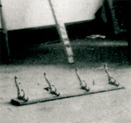
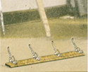
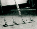
Let’s look at the Coatrack (see illustration 23A, B, C, D, and E) as a series of snapshots in time, just as we did to examine Duchamp’s hatracks, as he instructed us to do in his notes (refer again to illustration #1). Note that the geometriesof the coatrack series (as we also found in the hatrack series), isdifferent in every 2D and 3D representation. (For example, the ironhooks are straight in the 1964 Schwarz 3D model and 2D blueprint, whereasthey lean backwards in the original 1916-17 studio photograph and inthe 1941 Boîte print. And as in our treatment of the hatrackseries, we must mentally visualize or, alternatively, make literal 3Dmodels of the coatrack 2D representations, in order to observe the differencesamong all of the 5 coatrack representations (four 2D and one 3D). The particular distortionscontained within the original studio photograph provide the greatestinterest for our immeditate discussion. Again, as we found in the hatrack,the coatrack hooks bend and turn in unanticipated ways. (We expect mass-producedobjects to have characteristics of the factory-made, traits that includestandardization and regularity of form — the very opposite of custom-madevariations). Look at the last hook of the 4 (moving from left most hookto right), the top small sub-hook (the middle of the three sub-hooks)bends so far up and in that it reaches the top largest sub-hook. Duchamptold us that he nailed the coatrack to the floor after having “kickedit around” his studio. However, this trauma to the coatrack (that heaptly titled “trap” or Trébuchet — a term from a move in chesswhere a player sacrifices one of his own pieces to trap an opponent’spiece) the physical properties of cast iron determine that such a hookwould crack and break before bending. This rigidity of material provesuseful for withstanding the stress of hanging heavy coats. Duchamp,on the 1964 blueprint, even specifies that his 3D 1964 Schwarz hooksmust be made of iron — not soft copper. Testingand Comparison of Perspective Geometry: A Technique Applied fromCIA Expert Dino A. Brugioni in Photo Fakery
Click each image to enlarge
click images to enlarge
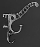
Note the shapes and count the holes in hook 24A and 24B and contrast these to the general form and number of holes found in Duchamp’s original Coatrack hooks in the studio photo and in the Schwarz model in 24C In fact, when Robert Slawinski and I began working on creating a coatrack 3D computer model (equivalent to the information contained in the 1915-16 2D studio photograph) we quickly recognized that the hooks used by Duchamp were; a) a common type readily found in the historical record (see illustrations 24 A and B); b.) that his 3D Schwarz model of the coatrack looked nothing like the “original coatrack” found in the studio photograph of 1915-16 (for example, note that the hooks are straighter in the 3D model and that the wood board bottom extends too far past the hooks on each end in comparison to what we find in the original 1915-16 2D studio photograph, see illustration 24; c) not only is the last hook (moving from right to left) distorted in the original studio photo above (in 24C) (its top small sub-hook with an impossible upward curve), but the other 3 main hooks of the four, and the wood board itself, are also distorted. In other words, we cannot take the matching historical hooks (as in illustration 24B), place them evenly on a symmetrically rectangular wood board and then find one single perspective viewpoint to make a projection that matches all the shapes of the coatrack, as Duchamp has depicted them in the original studio photograph (see illustration 23A). click images to enlarge
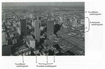
Illustration 25A depictsthe perspective found in photography — one fixed eye sees a continuousand related set of distortions from the perspective of this one eye.(The four different cube descriptions in 25A are what the eye sees from4 different fixed positions). Illustration 25B, however, more accuratelydepicts how we actually see objects, as our two eyes, head and bodiesmust continually move around 3D objects to fully see their forms, asshown with this cube. And yet, despite what must be the truly fragmentednature of the visual input, the mind and eyes work seamlessly togetherto create the appearance of discrete and fixed objects. The two cube examples(25A and B) directly relate to the earlier discussion of Duchamp’s WhiteBox note, which, as I argued, describes 2 mental operations (seeillustration 26A and B). The single fixed eye perspective of 26A islike the fixed eye looking at the cube in 25A; whereas the moving eyeof 26B operates like the multiple perspectives described in 25B. The notable difference between illustrations 25A,B and 26 A,B is the dimension. Using Duchamp’s terminology, 25A,B describes an eye in 3D space (“eye3“) looking at a 3D cube; whereas, 26A,B represents an eye in 3D space making observations of a 2D plane. Both 25B and 26B require time and movement in 3D space of the 3D eye ; whereas, 25A and 26A illustrate what Duchamp describes as the “vision” of the “same eye from a fixed point of view (linear perspective).”1 click images to enlarge
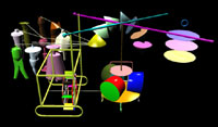
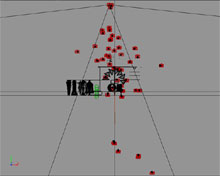
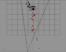
We made both physicaland computer models here in the lab. Our computer animation diagramsthe 6 cuts we believe that Duchamp made from 6 separate photographstaken in 6 different perspective positions. Robert Slawinski and myanalysis concludes that Duchamp used 3 whole hooks, 1 hook split into2 parts and 1 whole wood board as the 6 parts (from 6 different photos)as he assembled into what appears to be the single, whole and readymadecoatrack in his studio photograph. See Illustrations 28A, B, C, D, E,F, the 6 coatrack parts that Duchamp cut out and later assembled togetherare color coded (in these still images taken from the computer animation)to emphasize the separation of the part selected by Duchamp from therest of the coatrack (that he then discards, and that follows the sameperspective geometry of the targeted part.) click images to enlarge
This series of stills shows each of the 6 coatrack positions Illustration 29A and B show a comparison of the parts that Duchamp selected (in color coding) with an image that assembles the 6 whole coatracks, in their 6 different perspectives, together into one event simultaneously seen (using the same color coding). click images to enlarge
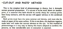
In addition to the evidence resulting from our analysis of the perspective geometries,2 other examples of internal evidence indicate that Duchamp used both”masking” and “cut and paste” techniques from thephoto alterations used in hobby and trade. Examine illustration30, a close up view of Duchamp’s original coatrack photo, revealingwhat a photo trick book calls the “fluffy edges” that caneasily appear as a soft whitish outline around a photo cut-out afterbeing pasted, if special measures are not taken. Forensic experts lookfor tell-tale signs — such as fuzzy contours– as indicators that photo prints have been combined. See illustration31A and B,two pages from “The Secrets of Trick Photography”by O.R. Croy discussing this particular problem within the cut and pastemethod. Our second exampleof internal evidence for our hypothesis that Duchamp altered his originalcoatrack photograph by combining parts returns us to illustration 23E.Only after making our animation analysis of the geometries in the coatrackdid I notice the potential importance of Duchamp’s “working”prints of the coatrack first published in 1983 by Ecke Bonk. These printswere described by Bonk as preliminary stages of Duchamp’s 1940 processin preparing pochoir prints for his publication of 300 copies of theBoîte-en-valise, (see illustration 32A and B). Bonk doesnot explain what the method was, or why Duchamp was cutting and pastinga separate paper cutout of the coatrack onto the background studio photo(where 3 hooks are masked out of the scene with white). Illustration32B indicates an attempt to position only the first hook of the cutoutonto the coatrack underneath. This “working print” also suggests(as judged by their two positions) that the paper cut-out coatrack isin one perspective view and the coatrack underneath, imbedded into thestudio photo background, is in another perspective. Compare this working print (32B) to our still from the video animation, where we concluded that Duchamp used 6 different viewpoints (cutouts of hooks and a wood board from 6 photographs), see illustration 32C. The similarity between 32B and C is striking. Was Duchamp using the same method of compositing multiple viewpoints into one coatrack for his pochoir print that he had used earlier to create his original coatrack in the studio photograph? click images to enlarge
I believe that this working print serves as a “smoking gun” in our case. Not only is the cut and paste method and the geometries of the forms similar between the alterations in the studio photograph and in Duchamp’s Boîte pochoir print, but his separate white-out and maskings of the wood board and the hooks now makes sense. For what purpose would the separate masking and treatment of the 4 hooks and the wood base serve (as is clearly indicated in his “working print”) other than as a matrix for creating a composite image?
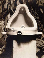
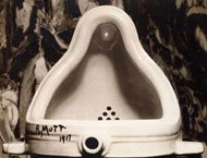
Related to evidence of photo compositing, as found within Duchamp’s “working print”of the coatrack, is a curious 2nd version of a photograph of Duchamp’sFountain urinal taken by stieglitz in 1917, and shown in illustration33A and B. William Camfield’s 1989 book, a chronicle of the odd historyof Duchamp’s Fountain urinal, presented this second stieglitzphoto for the first time after it quietly appeared within the archiveof Duchamp’s main patrons, the Arensberg’s, in the 1950’s. Before discussing the potential importance of this particular photograph, and its delayedappearance for spectators, let us again examine, as we did with thehatrack and coatrack, the consistent approach that Duchamp uses to presenthis readymades — as a series of snapshots over time — now appliedto Duchamp’s urinal.
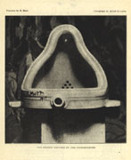
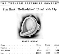
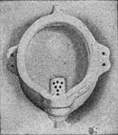
As we discovered when examining Duchamp’s hatrack and coatrack, the above set of urinal depictionsin 2D and 3D do not describe one consistent 3D urinal. For example,our analysis of the studio photo 1916-17 (illustration 34D found inthe 1960’s), the 1941 print (illustration 34C created from a 1916-17photograph) and the 1st version of the stieglitz photograph(illustration 34A published in the Blindman #2) reveals an inescapableconclusion — namely, that two different urinals were represented in1917. Again, our key question involves casualty — did Duchamp change urinals literally or photographically? Evidence for both hypothesesexists. Duchamp did make his original 3D miniature urinal model in 1940,and he did commission others to manufacture the full edition of 300.Surprisingly, after Duchamp authorized Schwarz to make editions of 14of his “readymades,” Schwarz failed, despite intensive search,to find even one of the 14 mass produced objects close enoughto Duchamp’s originals in 2D or 3D to serve as prototypes for the editions.Therefore, Schwarz had to organize the manufacture of all 14 editions himself. Stranger still, no duplicate urinal has even been found inany catalogue, including the literature from the very company that Duchampspecifically named his source for his urinal — the Mott company. One of the nice twists of history’s perversity is that, while theDuchamp Fountain exists in numerous replica versions, asurviving example of the original type of urinal has proven impossibleto locate. If it exists at all, it is now an item of exquisiterarity. Art historians WilliamCamfield and Kirk Varnedoe report that they strenuously searched thehistorical record for urinal models that matched the geometry of Duchamp’surinal. My own research agrees with their conclusion — that the closesturinal to Duchamp’s is a model called the “Panama” or “Bedfordshirewith Lip.” In the early 20th century, Mott, Crane andother distributers purchased urinals from Trenton Potteries, Trenton,NJ (a.k.a. “the sanitary pottery capital of the U.S.”). Modelsof urinals and other pottery products, such as toilets, were so basicand so infrequently changed that only freelance workers were neededto serve as modelers for the entire sanitary pottery industry. ASRLowns three of the Bedfordshire urinals, and all are stamped, “TrentonPotteries,” NJ; see illustration 35A. The duplication of shapeamong these urinals speaks both to the minimal variation that occursamong urinals, and to the easy standardization of form resulting fromtheir mold making process. Just as one hatrackstudio photo, found in the 1960’s, provided a closer match (but no cigar)to the Thonet historical model than any of Duchamp’s other 2D or 3Dhatrack depictions, his urinal in two studio representations (34C and34D) provide a close, but not exact, match to the Mott historical model(see illustration 35B,C and D,E). Duchamp’s two studio photo urinalsare here compared to the Bedfordshire urinal with lip from the ASRLcollection, placed in a similar position. The general appearance issimilar among 35B,C and D,E. However, the “side ear-like”brackets are larger and different, both from each other and from theMott model, as are the pipe connections at the urinals’ top and bottom.Moreover, we have concluded from our analysis that one should be ableto see Duchamp’s “R. Mutt 1917” signature and date (and one cannot)on a urinal when placed in both positions 35B and 35C, if the inscriptionwere indeed there. click images to enlarge
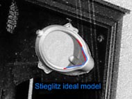
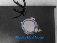
However, when we examine35B,C,D,E various attempts to place the Bedfordshire model in a positionto match the stieglitz photo 36A completely fail. Only when we compositetogether the top part of the urinal from one photograph, the bottompart from another and the drain holes and pipe hole from yet othersin different perspectives, does the urinal begin to look vaguelylike the stieglitz urinal 36A. Note that the bottom and top of the urinalsin 35B,C and 35D,E easily appear similar in size, scale and perspectiveview, whereas, in 36A, the stieglitz original photograph appears tobe in one perspective view in the top half and in yet another cameraviewpoint in the bottom half where the pipe connection rests. Moreover,when you look at our actual Urinal, 36D for example, the upper halfwith the drain holes looks further away from us in the photo; whereas,the bottom pipe hole part appears closer to us, in the foreground. Curiously,no similar “near and far” positions are transmitted by theforms in 36A, Duchamp’s 1917 stieglitz photograph. In fact,in our Bedfordshireurinal photos, 36B,C,D,E, the drain holes appear smaller, and thereforefurther away, and the pipe hole reads larger and therefore closer tous than in the 36A stieglitz photograph — giving credence to my observationthat the stieglitz photograph, strangely, does not depict the significantdistance between the back of the urinal and the front (as clearly indicatedin 36B).
We provide the 2D Interactive Presentation below to allow the spectator to experimentwith the cutting up and pasting together of different urinal photo parts.There are 9 possible combinations. One combination matches the stieglitzphoto. Also, try placing the pipe in the middle as we suggest. One canbegin to see how pieces that do not originally go together can be movedand will there appear to be better, or at least, equally correct intheir form, when in a new position — especially if you had the abilityto fill in gaps with even more cut-out parts then we provide in thispresentation.
More specifically, this Interactive Presentation places together the bottom part, cut fromthe entire Stieglitz original photograph (36A), with the mysteriouspartial version (also printed from an original negative) as the top.Perhaps, as in our coatrack example, where the working print probablyrevealed Duchamp’s methodology for compositing his coatrack togetherfrom a series of photos in different perspectives, perhaps this partialphoto of the urinal, printed and left as a complete image, representsthe smoking gun, also found to reveal similar evidence of being a photocomposite. For if we can, (1), easily create a likeness of the two 1917photos of Duchamp urinals using the Bedfordshire 3D models and yet,(2), run into difficulty when doing the same experiment by trying torecreate the 1917 Stieglitz original urinal photo with the same Bedfordshire3D model (the main difference being that the top part of the urinal,as in the partial Stieglitz photo, lies in one perspective and the bottompart in another), then perhaps the partial photo discloses itself asa step that Duchamp used in a process of creating his final photo composite,then aptly published in The Blind Man as he realized that wewould not readily see his alterations. (see illustrations 38A and B.)
Is this partial Stieglitz photo itself, that we see in illustration 39A, also made of parts? Andis the complete version of the Stieglitz photo (38A) essentially a fusionof yet more parts added to parts already composited in the top photoof the partial version (39A)? Moreover, is the fusing of different perspectivespassing as one perspective in Duchamp’s urinal, hatrack and coatrack,the same “rehabilitated perspective” geometry that he claimsto have been using in his Large Glass? Beyond “cut and paste” — what other photo tricks did Duchamp use? As previously described,I had suspected that the Stieglitz partial urinal photo representeda step in Duchamp’s photo compositing process, and that this photographicpart, was itself, perhaps, made of photo parts. Illustration 40B suggeststhat, indeed, the drain holes were added within the Stieglitz partialphoto, which, as a subtle but visible vestige, remains in the originalStieglitz photo, see illustration 40A. Note that in illustration 40B, when the contrast of light and shadow are amplified, the drainholes reveal a distinct boundary that is, unexpectedly, and withoutapparent reason, lighter in value, thus giving the literal appearanceof having been added as a patch. click images to enlarge
The urinal in the Stieglitz photo, shown close up and large, created a greater technicalchallenge for hiding alterations than in our previous examples of thehatrack or coatrack, that are depicted as farther away and small, andtherefore creating less expectation of perceiving visible detail. Sincehatracks and coatracks are, literally, made of parts (the hooks andwood base are all physical parts put together), photographic cuttingand pasting of parts can naturally exploit these predetermined and expectedjoinings, whereas, the urinal’s smooth and continuous, singular formdoes not offer such easy opportunities. Illustration 40C depicts yet another important piece among numerous pieces of evidence (pun intended).Porcelain urinals are molded forms that produce clean, clearly unambiguouslines and edges as shown in illustration 40D, E, F, (depictions of Bedfordshiretype urinals taken from Mott, Crane and Trenton Potteries cataloguesof the period [circa 1917]). Examine the circled area in illustration40C. The indefinite shadows and discontinuous lines and edges suggestthis lower left corner as a likely site of photographic compositingand retouching. click images to enlarge
We are presently working, along with forensic experts, on a substantial list of other odditiesfound within the Stieglitz photo (40A) including: (1), more precisedetermination of the nature of the distortions, first noted by WilliamCamfield, between the urinal in the foreground as depicted in relationto the painting in the background. We will also analyze and try to relatethe seemingly strange scale differences among objects in the Stieglitzphoto; such as the size of the urinal itself in comparison to the gaugeof the string tied to the left “ear-bracket”; or the relativelytoo large appearance of the rough hewn texture of the wood pedestal;(2), testing the feasibility of placing the urinal (whose actual form,not shown, is hollowed out underneath) so off center on the pedestal,as depicted on the photo; and (3), studying the strange shadows, lighting,as well as the peculiar reflections (reminiscent of pooling urine),in the top upper lip of the urinal — a pooling that appears to be defyinggravity. (If these reflections were actually urine, we would have tobe standing above, strattling a normally installed urinal in a novelorientation — with our backs against the wall looking down into thepool of urine and facing out to whoever would be peeing.) A second compositingmethod, beyond cut and paste, is suggested within the two studio photodepictions of Duchamp’s urinal, see illustrations 41A, B, C, D. A commonbut more difficult method of combining photo parts uses a dark or blackbackground (cardboard or cloth) placed into a scene with a correspondingspace left blank on the photographic plate in the camera. In this blankspace, a second image (not in the immediate scene) can then be seamlesslyadded into both the plate, and also into the (formerly) plain blackbackground. click images to enlarge
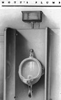
Two Photographs of Duchamp’s studio taken in 1916-17
Close-upviews of the Duchamp’s studio photographs (41A and 41B) Carefullynote the general blackened area behind the urinal in illustration41B and 41D and the dark cloth hanging directly behind the urinalin illustration 41A and 41C. Illustrations 42A, B, C, D show a few early examples from a 1898 book written for the general public, and titled, Magic; Stage Illusions, Special Effects and Trick Photography. Compare these four illustrations to illustrations 41 A, B, C, D, Duchamp’s two studio photos that depict his urinal. Carefully note the general blackened area behind the urinal in illustration 41B and 41D and the dark cloth hanging directly behind the urinal in illustration 41A and 41C. Not only do the other photo alterations, as previously discussed, exist in these two studio depictions (remember, the ghost figure in 41A and the likely cutting and pasting of the hatracks and shovels in 41A and B) but the urinal appears to be “applied” to the scene using the classic black background composite technique as the device. Look at our animation analysis in illustration 43A and 43B.
Four 19th century examples of the “black ground method” ofcompositing The irregular shadowing, unsure line and edges of the urinal’s silhouette(especially prominent in 43A) indicate a careful but, imperfect, maskingand transfer of the urinal onto the blackground placed in the scene.Note, in the animation, that the studio depictions of the urinal’s interiorlip shape, when outlined, comes very close to matching the form of ourstandard Crane/Mott/Trenton Potteries Bedfordshire model; whereas formof the interior lip on the ideal Stieglitz urinal (that is, when thedrain and pipe holes are corrected to be centered) is very different,see animation 43C. Of course, these data conform with my prediction(derived from my hypothesis) that the two studio photos are slightlyaltered representations of an actual Bedfordshire urinal (and, therefore,that a Bedfordshire model would predictably almost match.) However,a 3D model — even a corrected one — based upon the geometry in Stieglitzphoto would not match either the two studio photo urinals or the Bedfordshiremodel. As I have argued, the Stieglitz image is not representing, factualurinal different from either the 2 studio urinals or Bedfordshire model.I believe that the Stieglitz urinal is a photo composite madeof varied parts taken from photographs of an actual Bedfordshire3D urinal from different perspectives and at different scales). click images to enlarge
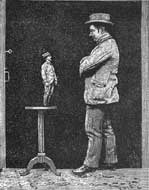
Looking back at the historical examples of the black background method of photo compositing,in 42C and D (now circled and labeled as illustrations 44A and 44B),we see how the compositing of separate images can play havoc with scale(when we see multiple images of the same figure taken at two differentdistances, we interpret these figures in the final photograph as smalland large sizes.) Other cues reinforce our interpretation of small andlarge figures standing side by side (as opposed to the small figuresuggesting greater distance, and the larger figure as the same sizestanding in the foreground). In illustration 44B, for example, the table’sposition in space (directly opposite to the larger standing figure),along with the feet of the small figure physically happening to meetthe table’s horizontal plane, immediately evokes our most absurd andimpossible interpretation — a real Tom Thumb! According to forensic experts, the only way to get a better grasp on why and how the scalesof urinal parts, and other objects in the Stieglitz photo look out ofwhack, is to determine as much as possible about actual sizes. For example,how large are the tags used at the 1917 Exhibition? (see illustration45A, of the Stieglitz photo with its tag circled.) The urinal looksdisturbingly small in comparison to the string, hang tag, and wood pedestaltexture. We have already determined, by our prior analysis, that the”ear-brackets” as depicted in the Stieglitz photo appear toolarge when compared to the actual Bedfordshire models of the period.Perhaps the ear-bracket [with the string and tag] are from a singlephoto taken at a different distance, a photo that was then fused withthe rest of the urinal parts?) Moreover, our forensic expert’s initial analysis echos my suspicion that the urinals in thetwo studio photos (45B, 45C) are, in addition to our sense that thescale of the urinals’ size is off, in comparison to the rest of theroom, most likely composited in, and also do not seem to hang accordingto gravity, (We need to try to measure Duchamp’s old studio room. Ifany original woodwork exists, we can learn a lot more about Duchamp’sphotos.) click images to enlarge
A closer examination of Duchamp’s 1964 urinal etching shows that, although Duchampdid base his tracings on the Stieglitz photograph to create this etchedimage, he, also and importantly, added a separate and specific extrapart — in a yet another perspective view, more radically differentfrom the rest. Note, when comparing illustration 46A, B and C with 47Aand 47B, the extreme leftward position that the whole urinal would haveto occupy (47B) for us to see this one urinal part in the upper rightside (47A). Why else would Duchamp move so far away from traditionalperspective in one exaggerated and isolated part of this drawing, ifnot from a desire to push his point further, probably because we arelikely not yet again to notice his new rehabilitated perspective systembased upon fusions of multiple points of view in his drawings, modelsor photographs. Remember this etching was done at the end of his life,in 1964. Duchamp had already exposed his new perspective system to theworld since his 1912 Chocolate Grinder painting and no one noticed.Moreover we continue to not notice because the mind creates and dependson such composites of information that Duchamp was presenting as perspectiveall the time. click images to enlarge
Given Duchamp’s claimthat he studied the entire section on perspective at the Paris’s mainlibrary, and that, it is a “no-brainer” to trace the basicshape of the Stieglitz urinal without mistakes, it would be difficultto believe that this extra and distinct perspective part added by Duchampto his urinal etching, would have occurred through accident or incompetence.We are especially encouraged to conceive of Duchamp’s extra perspectivepiece as intentional, since the rest of the etching captures the spatialrelations of the Stieglitz photo so well, including the pipe hole offsetto the left, and so forth. I must add one finalpoint to buttress my case about the urinal. In the quotation on perspectivethat I cited at the beginning of this essay, Duchamp claimed that headded language, in addition to anecdote, in his rehabilitated form ofperspective. Bonnie Garner suggested that when Duchamp signed his urinalMutt, he, in effect, communicated linguistically the same structurethat he used geometrically (with his fusing of multiple perspectiveparts into one whole). For what else is a “mutt” than an entiremongrel dog composited of many dog breeds (or parts) put together intime — an entity that only appears to be, in a traditional perspective,a low quality whole.
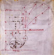
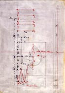
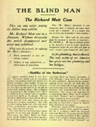
The other colloquialdefinition of mutt as “a stupid person” brings me backto thoughts about the first appearance of Duchamp’s urinal in TheBlind Man (1917). Not only was the Mutt urinal essay and image placedunder The Blind Man heading, but Duchamp and his close friendsalso(and, I believe, not coincidentally) used Duchamp’s ChocolateGrinder painting on the front cover, under The Blind Manbanner, as well — see illustration 48. I argue that thisplacement of the Chocolate Grinder painting with the BlindMan heading relates directly, in meaning, to Duchamp’s similar positioningof his urinal. For as spectators in 1917, we would have been specificallyblind to Duchamp’s new rehabilitated perspective used in bothhis Fountain urinal and Chocolate Grinder forms,as well as generally blind, as a consequence our foolish dependence(as Duchamp believed) on conventional perspective and “retinalvision” for determining factual reality. My discovery that the strangely distorted Chocolate Grinder uses the same systematic characteristic approach also found in the hatrack, coatrack and urinal (and a large set of other examples not discussed in this essay) returns us to Duchamp’s words that I used at the beginning of this essay — a quotation that now bears repeating. Duchamp: Perspective was very important. The “Large Glass” constitutes a rehabilitation of perspective, which had then been completely ignored and disparaged. Duchamp’s claims inthis interview (albeit cryptically) that he has done something rigorousand different to rehabilitate perspective, and that he has embodiedthis novelty in his new geometry in the Large Glass — with theChocolate Grinder as one part! In 1956 Duchamp stated”I was already beginning to make a definite plan, a blueprint forthe Large Glass. All of this was conceived, drawn, and on paperin 1913-14. It was based on a perspective view, meaning a complete knowledgeof the arrangement of the parts. It couldn’t be haphazardly done orchanged afterwards. It had to go through according to plan, so to speak.”In the Cabanne interview Duchamp further claims that “I had workedeight years on this thing, (the Large Glass) which was willed,voluntarily established according to exact plan. . .” Duchamp carefully provided us with his “Sears Roebuck-like” catalogue of notesand drawings describing his Large Glass project. Mostly writtenbetween 1911-15, these notes include a separate plan view and a sideelevation of the lower “bachelor half” of the Large Glass,(but no 3-D model) and a perspective drawing illustrating measurementsat 1/10 scale of the final Large Glass work, see illustration 49 A, B, C, D. click images to enlarge
Architects or engineersdepend upon similar plan views and side elevations as Duchamp’s Bachelorhalf to manufacture 3-D projects and small scale 3-D models. As discussedearlier, perspective drawings, in contrast, indicate the relative positionof a particular observer in visual relation to the object or building.A “precise and exact aspect” in the science of perspective(an “aspect” that Duchamp said he was interested in following),dictates that the perspective in the lower half of the Large Glassdrawing should relate to the geometry of the “blueprint” planand elevation. In other words, if you make a 3-D model following Duchamp’splan view and side elevation blueprints, you should readily be ableto find and replicate the perspective view that Duchamp depicts in hisperspective drawing by using this very same 3-D model. Most Duchamp scholarshave either accepted or praised Duchamp’s perspective skills. The problemremains, however, that I and a few other scholars have actually made3-D models from Duchamp’s plans — and none of us can find any oneperspective projection view that matches Duchamp’s perspective drawings!Moreover, the process of trying to recreate the Large Glass perspectivedrawing from what a viewer would see of the 3-D model via perspective(equivalent to what one eye or camera lens sees) quickly becomes maddening.When you fit one part of the Large Glass model to its projectionin Duchamp’s perspective drawing (say; part A, the ellipse in one wheelof the Chocolate Grinder, for example — see illustration 49A),the rest (parts B through Z) immediately fall out of place. We losethe fit of part A, and all the other parts C through Z, once part Bis matched — etc. We may then be temptedto somehow change the plans so that the perspective projection, as laidout in Duchamp’s actual Large Glass, can be generated from the3-D model (built from the plan and elevation view) — which is, in fact,what some scholars have done. But that’s cheating, and such a providencealso assumes that Duchamp was incompetent, or did not care about accuracyof perspective, although he claimed otherwise in earlier interviews,as well as to Cabanne. If both the plan viewand side elevation construct a consistent 3-D model of the ChocolateGrinder and the overall Large Glass itself, how and why haveI and other scholars failed to generate a similar, if not exact, perspectivedrawing from this 3-D Large Glass model? I will argue that thereason why we cannot generate a single perspective view (in duplicating,what should has been the process that Duchamp followed to create hisperspective drawing) must be Duchamp himself did not used perspectivegeometry, but, rather his new rehabilitated perspective — the methodthat created his perspective drawing and the Large Glass (a.k.a.The Bride Stripped Bare by Her Bachelors, Even 1915-23.)
If we analyze theparts of the Large Glass (a 2D perspective view), using a 3Dmodel constructed from Duchamp’s plans, we can only duplicate the depictionsin what is rendered in Duchamp’s Large Glass 2D perspective drawingwhen we move our eye in time around the Large Glass 3D modelto collect snapshots (cuts), and then fuse these separate perspectiveparts together into one depiction — the very same method that Duchampuses in his coatrack, hatrack and urinal 2D representations. Recallthe illustrations (now #50A,B) showing the different perspective depictionsresulting from 4 different fixed eye positions, in contrast to an eyethat moves around a cube. Illustration 51A,B, C present three animations from our analysis of Duchamp’s ChocolateGrinder and Large Glass in 2D and 3D. The first animation(51A) shows the camera’s perspective while moving around a 3D modelof the Chocolate Grinder in 3D space. Colors highlight the partthat corresponds to the equivalent section of the 2D Chocolate Grinderin the Large Glass perspective drawing. In other words, the animationshows a position that both the camera and 3D Chocolate Grinderwould have to occupy to create the particular 2D Chocolate Grinderpart shown in color code.
The next animation,51B, shows our 3D computer model of the Chocolate Grinder asfundamentally based upon Duchamp’s 1913/1934 plan view and side elevationplans. The animation further depicts how the position of the cameradetermines the particular set of distortions seen by the lens in anyone 2D snapshot of the 3D Chocolate Grinder. Moreover, this animationdepicts that once one camera position allows a match in one part ofthe Chocolate Grinder, the other parts of the Chocolate Grinderand the Large Glass depart from this single perspective position.When other Chocolate Grinder parts are matched, each exists inits own perspective framework. Our efforts to tame all ChocolateGrinder parts into one perspective view, slips hopelessly away witheach successful match of a single part, and the consequent completerejection of the rest in lock step. The next animationsequence, 51C, illustrates the cut and paste method that Duchamp probablyused to create not only his Chocolate Grinder (and also his coatrack,urinal, hatrack, etc.), but the entire bottom half of the Large Glassitself. As any one photograph yields a single perspective view (withits own particular distortions), Duchamp’s selection of one part fromeach snapshot, after he pastes them together, creates a multiple fusionof varying perspectives. The last frame, showing the Large Glassin color coding, indicates each of the (approximately) 43 parts thatlive in their own perspective world, see Illustrations 51D and 51E.Due to perspectiveconstraints, we would have to move one eye or lens 43 times in 3D spaceto actually see the same information that Duchamp shows us in his singleLarge Glass work! Illustrations51F and 51G map the 43 camera positions in relation to the LargeGlass 3D model that produced the 2D color coded projections in 51Dand 51E.
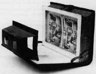
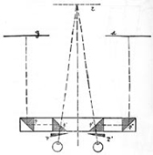
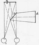
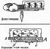
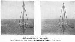
Duchamp’s Revolutionary Alternative Within the larger Victorian framework of technological mania, the human desire to developa better system of representation for expressing how we see the worldevolved into a frenzy of public interest and private invention. Theadvent of stereoscopic drawings quickly led to a whirl of experimentsamong the expanding developments in stereo photography and moving pictureimages. Stereoscopic devices depend upon the mind’s ability to fusetogether two 2D images that, when seen side by side at the same time,create an impressive 3D effect. (One 2D image is drawn and seen in theperspective of the left eye, and the second 2D image rendered and thenseen when displayed in the position of the right eye). Seemingly endlessvariants and extensions of stereoscopic concepts and equipment weredeveloped and patented into the early 20th century. The useof various prisms, or mirror systems, in numerous combinations, ledto even more unusual attempts to create stereo fusion with, for example,the use of three images, instead of two, for two eyes. (See illustrations52A,B,C,D,E and F.)
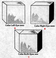
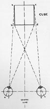
The limitations ofhuman perception and cognition lie at the center of our illusionaryexperiences evoked by 3D stereo vision or even by “moving pictures,”where projections of film, when speeding by fast enough, appear continuousbecause our eyes and minds are, literally, too weak to detect separationsbetween the 2D images. Moreover, it requires no great leap, for someoneas intelligent as Duchamp, to understand that these 19thcentury optical experiments expose not only this retinal weakness, but(and more importantly) also suggest, in general, how perception andcognition work. We learn that our eyes and minds take bits of information(from the past and present) and seamlessly fuse them together. However,what we actually think we see, unless we become directlyanalytical and override this automaticity,is much more dominated by a mental construction than we consciouslyrealize. For example, when we view a depiction of a cube, we are essentially guessing that this object is a cube, basedupon both the direct information that we have in illustration 53 andupon prior experience. The idealized construction of”cubeness” in our minds completely erases the additional informationof the cube thatour two eyes literally see. In illustrations 54A,B, and C, twoviews of the same cube are separately represented as seen by the leftand right eyes (54A,B), whereas 54C is the amount of information thatboth eyes actually see. Illustration 54D shows a schematic plan (inbird’s eye view) of two eyes’ field of vision and fusion when lookingat a cube.
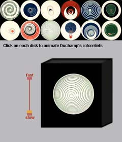
We obviously see moreinformation with stereovision’s two eyes than in photography and perspective’s”one-eyed vision.” The mind’s action of fusing two 2D imagesinto a single 3D experience has also raised the dimension of our perceptionand, therefore, also increases the information available to our senses,as shown in illustration 54C. Not everyone possesses the ability tosee representations in stereo. Severe astigmatism, or blindness in oneeye makes the 3D fusion of two 2D images impossible. In early bookson stereo vision, 19th century experiments that tested thepossibility of an optical device that would allow a single 2D imageto be seen as 3D with only one eye were cited and ridiculed as obviouslyfated to fail. The research of Stephen Jay Gould and me reveals thatDuchamp himself was the first person, even before any scientist succeeded,to develop a system and a device (1923) that produced a 3D stereo fusionin the mind with a single 2D image seen by a single eye. Try the InteractivePresentation in illustration 55. Duchamp’s Rotorelief Discs (1935)surprisingly produce an even greater 3D effect when seen by one eyethan by two. Click on any disc to select. Control speed by clickingon bar and dragging bar up and down (with depressed clicks) betweenfast and slow. Duchamp first made his Rotorelief Discsfor phonographic record playing speeds, 78 or 33 3/1.
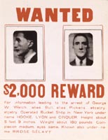
Duchamp created many other experiments using stereoscopicpairs. He included two examples in his Boîte-en-Valiseminiature museum (Figs. 56A and 56B). These two stereoimages weremade by Duchamp in 1918 and 1920 but not published until 1941.As I discussed at the Harvard symposium Methods of Understandingin Art and Science: The Case of Duchamp and Poincaré, Duchamp’spreviously unrecognized stereo experiments, as detectedby my studies, include one work, the Wanted Poster (1921),that was (since 1941) viewed as a “readymade” object thatDuchamp only altered by personalizing the object with photos andtext referring to himself. (See illustration 57A and 57B, theWanted Poster print, first seen by spectators in the Boite-en-Valise(1941), as the original Wanted Poster (1921) work is “lost.”
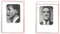
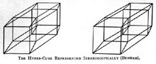
I noted that the redand blue colored boxes and the two portrait photos (of what may be,even in Duchamp’s original photo source used to recreate his work, aretouched composite of Duchamp and someone else — a criminal perhaps?)are asymmetrically placed and shaped. In other words, the left Duchampimage is higher than the right image, and the lines of the boxes themselvesare strangely designed to be uneven. I noticed one day that both thesize and the separation between the 2 boxes seemed similar to a commonstereo card. I scanned, printed and then cut off the top of the WantedPoster at a duplicate size in the Boîte-en-Valise folder(56B) and then placed it in to a stereo viewer. When seen in stereo,the two asymmetrically shaped boxes in the Wanted Poster unexpectedlyfuse into one symmetrical box. I now could see a single Wanted Posterimage of Duchamp’s head that allowed me to see the front and side ofhis head all at once — a single viewpoint that would not be possiblefor 3D eyes in 3D space. This visual result, I believe, expresses Duchamp’sverbally stated interest in extending a continuum to include transformationsamong 2, 3 and 4 dimensions. (See illustration 58, showing atraditional stereo card that reflects the popular and technical interestin 4D space and objects in the early 20th century. This 2Dstereopair, as seen here, depicts a 4D figure in two different perspectiveviews. When seen in a stereo viewer, the dimension will then be increasedinto a single 3D view of this same 4D object, also shown in 2D. Using what Duchamp called a 4D eye [eye4], only 4D space allows us to see 3D objects 360° in the round in one instant; whereas, in 3D space a 3D eye (eye3) must move in time around a 3D object to collect 2D observations (thus reducing an object from 3D to a series if 2D shapshots). Only after these cuts are fused together, can we recreate in our minds a sense or approximation of any actual 3D object in the round (thus increasing the dimension when transforming a series of 2D cuts into a 3D object). Duchamp’s note, illustration 59, uses the fist’s ability to hold and experience the form of a 3D object, all at once, as analogous to what would occur in 4D vision. Illustration 60, a portrait photograph of Duchamp, also mimics what could only be simultaneously seen in 4D space. This portrait is also similar to the experience evoked when seeing the two Wanted Poster heads and lined boxes in a stereo viewer. Significantly, Duchamp selected this very photo (60) as the cover for his own catalogue raisonné design in 1958. click images to enlarge
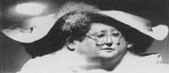
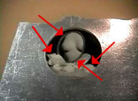
With Duchamp’s undergroundexperiment in the Wanted Poster, we may have increased our informationwith a 4D experience, but the data provided by Duchamp’s head are stillincomplete. Panoramic painting and photography represented yet another19th and 20th century experiment and approachto packing even more 3D information into 2D images. Illustration 61shows a “panoramic” view of a woman’s head. The photo uncomfortablyreads as if a 360° view of the woman’s head were rolled out, like cookiedough, onto a 2D plane. Such a panoramic photograph, by allowing usto see a 3D object (such as a head) on all sides at once, certainlyyields more 3D information in
2D than stereo experimentscan provide, and also offers a perspective of something not possiblein our normal 3D vision in 3D space. Yet, because the distortions producedby the panoramic technique, as seen in illustration 60, are so viscerallyrepulsive (probably because they evoke a sense of seeing flayed skin– the only way to make such a flat geometric view literally possible),and so foreign to our actual experience, we are unable to disregardthe panoramic distortions, whereas we routinely, and without effort,ignore or seamlessly filter out perspective distortions. Therefore,we can conclude that the panorama presents an interesting representationaleffect that would not challenge perspective photography as a dominantor popular convention.
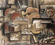
Cubism, in addition to its status as the beginning of one of the two biggest revolutionary departures in art (the other being the advent of perspective itself in the Renaissance), emerged, for Duchamp and others, as yet another experiment and alternative to static perspective representation in the larger cultural context of the early 20th century (see illustration 61, a cubist painting by Picasso). * Part IV through VI will be published in Tout-Fait, Perpetual 2005. Illustrations 2A-2F, 12A-D, 13B, 14A, 15A, 16A, 17, 18A-B, 19A, 20A-C, 21A, 22A-B, 23A-E, 32A, 34A-H, 41A-D, 46B, 49A-D ©2005 Succession Marcel Duchamp, ARS, N.Y./ADAGP, Paris. All rights reserved. |
||||||||||||||||||||||||||||||||||||||||||||||||||||||||||||||||||||||||||||||||||||||||||||||||||||||||||||||||||||||||||||||||||||||||||||||||||||||||||||||||||||||||||||||||||||||||||||||||||||||||||||||||||||||||||||||||||||||||||||||||||||||||||||||||||||||||||||||||||||||||


![Ear-bracket [with the string and tag]](/issues/issue_3/Multimedia/Shearer/images/45A_small.gif)